IBM PC Pictures
Motherboard

This is the IBM 5150 mainboard. All components apart from the BIOS containing IBM's proprietary code were commercially available from third parties. The board itself is large, measuring 355mm by 304mm. The memory is held in 4 banks in the top-left quarter - bank 0 is the one closest to the ROM chips in the middle of the board, and bank 4 is on the far left. Each 64 KB RAM bank consists of 8 IC sockets - the image above shows all four banks populated, so this one has the maximum 256 KB of RAM. The banks must be populated in order, i.e. bank 0 first, then bank 1, then 2, etc.

All the ROM chips are in the middle column of the board, to the right of the memory banks. The single BIOS chip in the 5150 sits in socket U33. Three versions of the BIOS exist - they are:
Part #5700051, dated 04/24/81
Part #5700671, dated 10/19/81
Part #1501476, dated 10/27/82
In addition to the BIOS, the board also has a ROM which holds "Cassette BASIC" which holds the BASIC interpreter as well as the cassette routines for storage and retrieval of programs. Microsoft's floating-point math routine in the firmware of this chip was released with a bug - if you ask the system to divide 0.01 by 10, it displays 9.999999E-4, instead of the correct answer of 0.001. By default, the IBM 5150 "booted" into Cassette BASIC unless there was a system disk in the drive.

This is the CPU - P8088 - an Intel 8088 running at 4.77 MHz. IBM shipped the 5150 with CPUs from AMD and other approved Intel 8088 manufacturers in order to secure a consistent supply.

To tell the mainboard what hardware configuration existed, the mainboard had two sets of DIP switches - these were used to declare the amount of memory installed, what type of monitor was connected (colour or monochrome), and whether a math co-processor was installed. Later PC clones ran a piece of firmware accessible by pressing and holding a specific key on initial startup, e.g. AMI, Award or Phoenix BIOS, but back in 1981 high-capacity ROM chips that could store the configuration and diagnostic software were very expensive - as such boards got hardware switches and the software was supplied on disk.

Only three connectors exist on the mainboard - the 12-pin power socket, the keyboard connector, and cassette connector. The latter two are both 5-pin DIN sockets. The one closest to the power connector is the keyboard socket.
Monitor

The IBM PC Model 5150 with 5151 12" monochrome monitor. This was driven by the IBM Monochrome Display Adapter (MDA).

And here's a zoomed-in shot of it. The knobs on the right are for contrast (top) and brightness (bottom). The contrast knob fixes the contrast at the current position when pushed in; when pulled out you can adjust by turning the knob.

This is what the 5151 monitor looks like from the back.

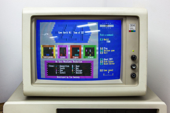
The IBM 5153 13" Color Monitor, designed to be paired with the Color Graphics Adapter (CGA). In 1981, this would have set you back $680 for the monitor alone. The brightness and contrast knobs are the same as on the 5151, but the 5153 got a front power knob too!
System Unit

The front of the "system unit" contains some vent holes for cooling and two full-height drive slots. Typically the early 5150s came with a single 5.25" floppy disk drives (the left-hand bay would have been filled with a black blanking plate). These were frequently upgraded later to support dual 5.25" floppy drives or a 10 MB hard disk.

The rear of the system unit has the following from left to right: monitor power out, power in, power supply fan vent, keyboard DIN socket, cassette DIN socket, and 5 expansion slots.

The top of the case slides forward after removing 5 screws (2 on early 5150s). This one is a later 5150 that has the 16K-256K motherboard because it has the "B" stamp at the top, and the power supply is silver (in early 5150s these were black).