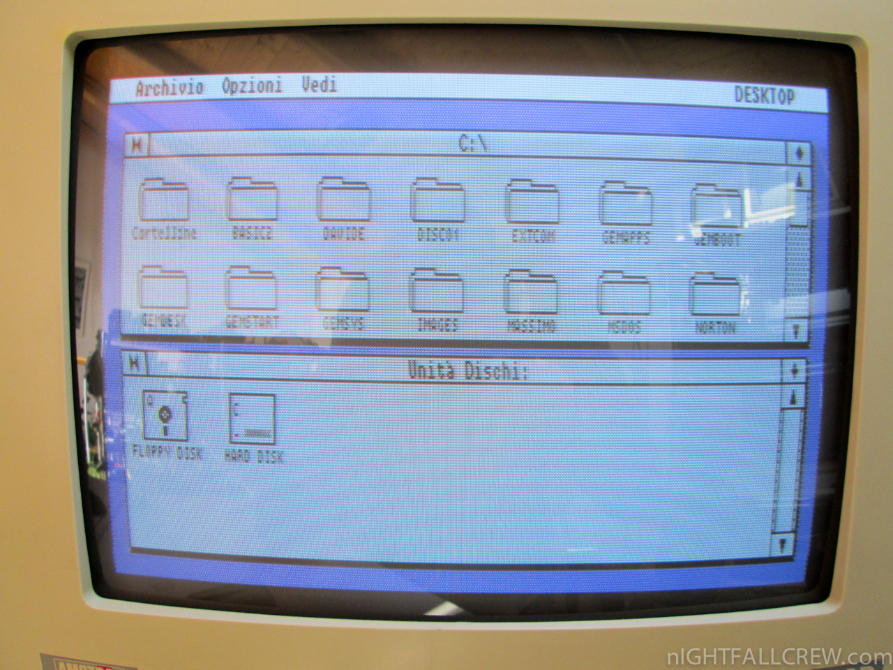
Amstrad PC1512 and PC1640 Pictures
The Motherboard
The PC1640's motherboard was actually based on the PC1512's design, complete with the PC1512's CGA video logic still embedded on the PC1640's board, but disabled. According to Roland Perry who was on the design team at Amstrad, it was still cheaper for them to build them in this way rather than removing the old CGA circuitry for the PC1640! The PC1640 of course also had the Paradise EGA video circuitry embedded on the board, which is wired up so that it appears to the system like it's an external card on the ISA bus.
Due to Amstrad's PC1512 getting bad press for not having an upgradeable video card, the PC1640's design added an enable/disable switch for the EGA circuitry, thus allowing an ISA video card to be an optional upgrade.
This is the PC1512 mainboard (part number MC0032B or MC0037B), with the unpopulated 128 KB memory expansion area highlighted in red. Note the three 8-bit ISA expansion slots in the top right. Along the top are a 25-pin serial port, 25-pin parallel port, a DIN socket for the monitor, and a DIN socket for the keyboard.
This is the PC1640 motherboard (part number MC0040E or MC0042D). The Intel 8086 CPU running at 8 MHz right in the centre and the math coprocessor socket (empty) above it. 640 KB of DRAM chips in lower left, with the two main ROM BIOS chips just to the right of them. Note the monitor connection has changed to be a 9-pin DSUB instead of the PC1512's large DIN connector.
This is the microprocessor, MBL8086-2, which is a Fujitsu-manufactured Intel 8086 running at 8 MHz. In this particular case the chip has a manufacturing date of 8804 (4th week of 1988). It's a plastic DIP-40 package. Some boards got an AMD-branded 8086-2.

Here is a close-up of the PC1640's 640 KB RAM bank, which is a 2 x 9 block of 256 Kbit chips, rated at 150ns. To the right of the memory are the two ROM BIOS chips, part number 40043 (even addresses) and 40044 (odd addresses). Both were 16 KB in size, making a total BIOS firmware size of 32 KB. Back in 1987 it was quite common to have the BIOS split across several chips.
BIOS settings on these Amstrad models was changed and stored via a DOS utility called NVR, which stands for Non-volatile RAM.

These two large ICs have Amstrad part numbers 40039T and 40041T. The former is the bus gate array. The latter is part of the overall chipset, but I'm not sure what its purpose is.
A summary of the main ICs on the PC1512 and PC1640 boards is as follows:
| Chip Identifier(s) | Purpose |
|---|---|
| AMSTRAD 40040T | Amstrad MGA (Memory Gate Array). Also found on PPC portables and the Amstrad 2086. |
| AMSTRAD 40042 | Keyboard controller (Intel 8048). |
| AMSTRAD 40043/40044 | Amstrad 32K ROM BIOS (even/odd). |
| AMSTRAD 40039T | Amstrad BGA (Bus Gate Array). Also found on PPC portables and the Amstrad 2086. |
| AMSTRAD 40045 or 40078 | Amstrad VDU Character ROM (40078 has greek characters) |
| AMSTRAD 40041T | ? |
| AMSTRAD 40100 | EGA ROM |
| National Semiconductor INS8250N-BT | UART (for Serial port communication) |
| Fujitsu MBL8259A-2 | PIC (Peripheral Interface Controller) |
| NEC D8253C-2 | PIT (Programmable Interval Timer) |
| Hitachi HD146818P | RTC (Realtime Clock) |
| Zilog Z0765A08PSC -or- NEC D765AC -or- UM8272A |
Single or Double-density floppy disk controller (FDC) |
| NEC D8237AC-5 | DMA (Direct Memory Access) controller |
| NEC 8617X5 | DMA (Direct Memory Access) controller |
| Paradise PEGA 1A 38304B | "IGA" (Integrated Graphics Adapter) - a Paradise EGA chipset - also sold as the PC Chips G3101. Provides Hercules, CGA and EGA modes. |
| Sanyo LM33256-15 | DRAM (Dynamic Random Access Memory), 150ns |
| NEC D41264C-15 | Video DRAM, 150ns |
Keyboard and Mouse
Both computers got an 85-key keyboard, with the only difference being the logo strip along the top which indicated the model of PC:
Despite the layout of the Amstrad keyboards closely resembling the 84 keys of the IBM PC and XT, they are electrically and mechanically incompatible (Amstrad keyboards produce different scancodes when a key is pressed to those produced by an IBM-compatible XT or AT keyboard).
The extra key on the Amstrad keyboards is the Del-> key above the Return key.

The Amstrad 2-button serial mouse that came bundled with both the PC1512 and PC1640 was an awkward shape and not particularly nice to use. It plugged into a DSUB port in the top-left of the keyboard. You could also remove the mouse and plug a joystick into this port and the PC would read specific scan codes when the joystick was used.
Monitors
The various monitors available for the PC1512 and PC1640, with sample output are shown below. The MM and CM monitors were those that were bundled with the PC1512, and the MD, CD and ECD ones were bundled with the PC1640. The pinouts of the connectors are different between PC1512 and PC1640 monitors, so they are *not* interchangeable.
The PC1512's monitors use a proprietary 8-pin DIN socket to send video signals from the system unit to the monitor. The PC-MM and PC-CM pinouts are the same, so you can upgrade to a PC-CM monitor from the PC-MM on a PC1512.
The PC1640's monitors all use a proprietary 9-pin DSUB connector. The same pinouts are used regardless of monitor type, but the system will interpret what the pin's function is supposed to be (e.g. SW8 on the DIP switch block grounds pin 2 when off, or it routes it to the "secondary Red" signal when on).
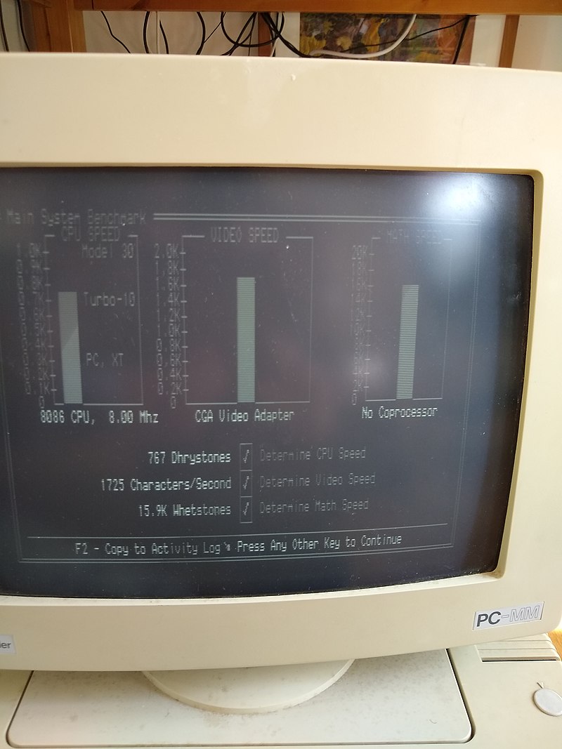

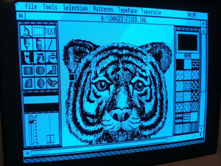
Amstrad PC1512 PC-MM
(monochrome CGA)


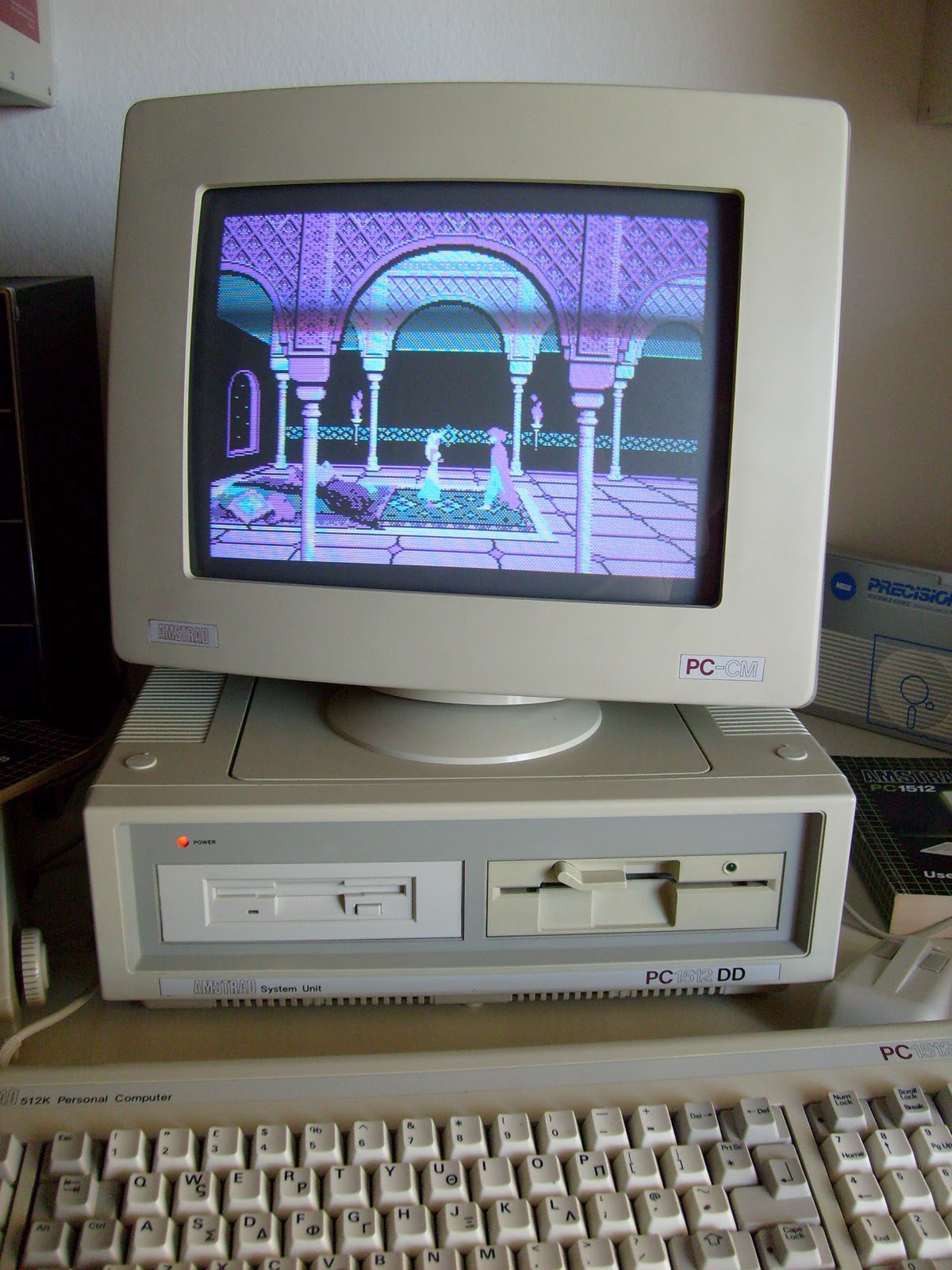

Amstrad PC1512 PC-CM (colour CGA)
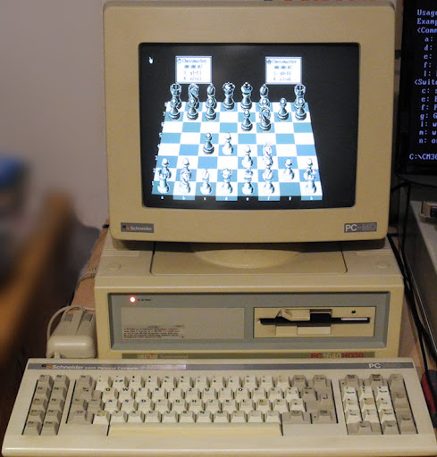


Amstrad PC1640 PC-MD (monochrome CGA)


