TAPE TOPICS
Schematic
Tighten the frequency window
by Carl Evans
We have discussed many aspects of the 410 Program Recorder, traveling a long road from the properties of magnetic tape to the functional block-diagram in the last issue. Now we unveil the long-promised schematic diagram for the digital playback circuit in the 410 Recorder and show you how to upgrade the circuit to obtain more reliable CLOADs. I will also answer a number of reader questions in our new Tangle Angles section.
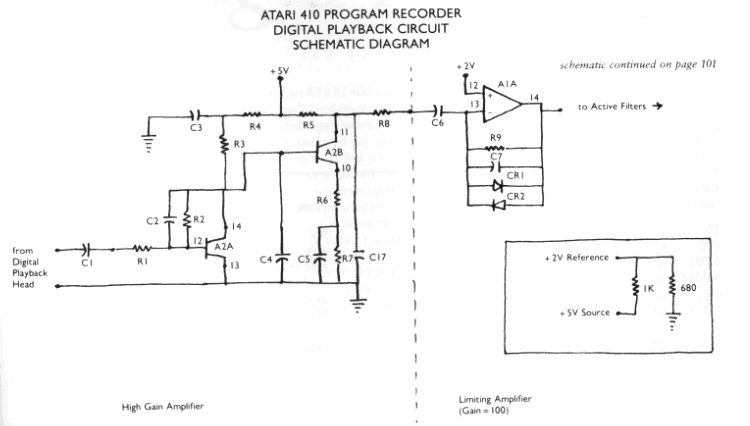
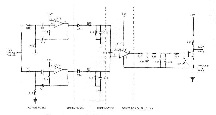
 Figure 1 shows the schematic diagram of my 410 Recorder. I strongly
suspect that there are many different 'models' of this recorder carrying
the 410 trademark. Therefore, I can not guarantee that this schematic will
match your particular recorder, but the four units I have been able to examine
do match this diagram. The schematic is arranged in the same format that
I used for the functional block-diagram in the last issue.
I mentioned a while back that there is a 'reliability fix' that you can make on your 410 Recorder. The 'fix' is really quite simple once you have a schematic to follow. All you have to do is replace a few ten-per-cent resistors with their one-per-cent brothers. You can get the needed resistors at most electronic supply stores. I got mine at Radio Shack.
The resistors to replace are the ones in the feedback loops of the two active filters. Specifically, I am referring to the 240K-ohm, l/2-watt resistor and the 330K-ohm, 1/4-watt resistor. Replacing these two resistors will 'tighten' the window of frequencies that will be interpreted as data. In addition, I recommend that you replace the ten-per-cent tolerance 56K, 5.6K, 68K, and 7.5K, 1/4 watt resistors which you will also find in that part of the circuit. I must caution you that any tampering of this type will void the warranty on the recorder, so you should wait until the warranty expires before making these modifications.
Don't worry about replacing the wrong resistors. None of the circuits in the recorder will be degraded by such a mistake. If you are in doubt about which particular 330K-ohm resistor to replace (there are three in the machine), then just replace all of them.
I have not yet seen one of the new ATARI 1010 Program Recorders. I plan to report later this year on the new recorder. It should be interesting to see if Atari has improved the design any
The rest of the department this time is devoted to answering some of
the letters you have sent in. Keep those letters coming. In the next issue,
I will talk about the audio playback circuit and show you the schematic
that I came up with for it.
ATARI 410 Program Recorder Digital Playback Circuit Electronic Parts
List
DISCRIPTION                                                      LOCATOR
------------------------------------------------------------------------
RESISTORS (1/4 Watt unless otherwise noted)
47                                                                    R6
470                                                               R4, R7
1K                                                            R1, R5, R8
4.7K                                                       R20, R21, R22
5.6K                                                                 R13
7.5K                                                                 R12
10K                                                              R3, R24
15K                                                             R16, R17
56K                                                                  R11
68K                                                                  R10
100K                                                                 R23
240K (1/2 Watt)                                                      F15
270K                                                                 R18
330K                                                        R3, R14, R19
1MEG                                                                  R9
------------------------------------------------------------------------
CAPACITORS
(VALUE)        (VOLTAGE)      (TYPE)
50      PF        50           disc                               C2, C7
820     PF        50           poly                     C8, C9, C10, C11
0.001   UF        25       axial ceramic                         C4, C14
0.0047  UF        50       axial ceramic                        C12, C13
0.01    UF        25       axial ceramic                         C6, C17
0.033   UF       100           Mylar                            C15, C16
0.1     UF        25       axial ceramic                              C1
4.7     UF        35     radial electrolytic                      C3, C5
------------------------------------------------------------------------
IC LM   324     OP AMP                                      A1, A1A, A1B,
                                                                A1C, A1D
IC LM   3086N                                               A2, A2A, A2B
DIODE   IS2076                                        CR1, CR2, CR3, CR4

Tangle Angles
This forum for resolution of problems with cassette tapes and the Atari Program Recorder features responses to your letters. Space requires us to edit your letters to the essentials. Some letters duplicate the problems of others, so will not be printed. Therefore, if you have written, watch for your problem to be reflected in the letters and answers we do print. Some of you ask for an individual or prompt answer. If you include a self-addressed stamped envelope I will try to comply. When writing, be as specific as you can, especially if problems persist after you have tried techniques I recommend. If you discover something you think helps, send that too. We're all in this together. -Carl Evans
I have an ATARI 400 and 410 recorder, and can't load programs reliably. Prerecorded tapes work, but my own go sour. I swapped my original recorder for a new one, but it's still not working. I notice a hiss with my tapes that is not there on prerecorded. I think this is due to DC bias used to erase my tapes. Perhaps hiss is being read as FSK and giving bad data. I disconnected my erase head and now bulk erase my tapes. Of course, the real solution is to "narrow the window" on the decoders.
Do you know a way to get a schematic on the 400 computer? I want to add "video out." Also, can you use the 400 with a disk drive?
Gary Pearcy
Stone Mountain, CA
Your tape hiss problem is most likely due to a bad diode in the limiting amplifier portion of the playback circuit. Your solution, while effective, is a bit drastic. Check the two diodes in the limiting amplifier and replace the bad one. If the problem comes back, then the gain of the front-end amplifier is probably too high. If that is the case, then you will have to measure the gain and calculate the value of a new gain resistor to lower the gain. A real quick check is to measure the DC voltage between pin 11 and pin 4 (ground) of the l/O cable. With a tape being played, this voltage should be about 3.6 VDC. If the reading is zero, then replace the LM 3086N IC. Any other bad reading means that the limiting diodes (152076) are probably bad. Also, if either pin 1 or pin 7 fail to have any non-zero output, then you will have to replace the LM R74 OP AMP IC.
Detailed schematics for the ATARI 400/800 are supplied with the Atari Technical User Notes which are available from Atari for $29.95.
The ATARI 810 Disk Drive will work quite well with any ATARI 400 that has at least 16K RAM. However, I recommend that you have at least 32K RAM.
I intend to beat my recorder problems because of my tight budget, and because I don't want to be bested by a machine.
1. I get lots of errors 138, 140 and 143., These often have line numbers (e.g.. ERROR 143 at LINE 19275) even when the program has no such line number. With a new tape, my recorder worked all right for the first read of test programs; but after modifying the programs slightly, and copying back on the same tape, I got an ERROR 143 on the first try, and ERROR 138 on the second try.
2. The footcounter slips when rewinding or advancing, so it is of questionable accuracy for finding programs .
3. I'd like to get multiple programs on tape, but don't like to skip ten feet of tape between programs. I'd rather put them close together so the audible end of one program signals the beginning of the next.
4. The Atari Reference Manual doesn't mention what really happens with PRINT and INPUT statements used with tape. Not a word about the need for an End of Line signal between each item. Thanks to Lon Poole for that info.
5. Any chance the Atari Recorder will be able to look for programs on a tape by name?
Dale Myers
Worthington, OH
1. Try bulk erasing each tape before you write on it, and clean your play/ record heads per instructions in the 410 Operators Manual.
Your problem might be that the limiting amplifier may not be limiting properly. Measure the DC voltage between pin 11 and pin 4 on the I/O cable. The voltage should be about 3.6 VDC when a tape is playing. If it is not, then check the diodes (l S2076) in the feedback loop and replace them if they are bad. A zero voltage under these conditions means that you will have to replace the LM 3086N IC. Also check the voltage between pin 1 and pin 4, and pin 7 and pin 4 while a tape is playing. If either reading is zero, then replace the LM 324 or AMP IC.
2. The meter mechanism on the 410 Recorder seldom works very long or very accurately. TKO belt drive system is very sloppy and is at best unreliable. This is one of the reasons that I recommend putting only one program on each side of a cassette tape.
3. Storing more than one program on each side of a tape is recommended only for archive purposes. The retrieval problem is error-prone and tends to be too time consuming for everyday use. There are two reasons I suggest a 10-foot count on the meter between files. First, it is possible to destroy a good file by over-writing the End-of-File marker if you don't space forward at least a little bit. Second, for archive applications, I fast-forward a tape to about where I think the desired file is (remember, the foot counter doesn't work reliably) and listen for a section of blank tape to help me locate the next file.
4. The need for EOL markers between data blocks is explained in the Technical User's Notes which are available from Atari.
5. Sorry, it is not feasible to make the ATARI 400/800 look for cassette file names.
ANTIC promised to tell ATARI owners how to increase the baud rate on cassette loading from 600 to 2400. Is this possible? Would it be a software-implemented method or would it require hardware modification?
W. D. Creegan,
President
Prescott Atari Club
Prescott, AZ
Yes, it is possible to increase the baud rate of cassette tapes. Theoretically, the upper limit for the ATARI 400/800 is about 1400 baud. Practically, however, the upper limit is about 600 baud (the default baud rate used by Atari). The reasons are complicated, but a simplistic explanation is that the FSK data system that Atari uses is naturally sensitive to frequency deviations. At high baud rates these deviations are accentuated. There are two solutions to this problem. The first is to use a tape recorder with a lower WOW and Flutter rating. The second is to use chromium tapes. The first solution is the best, but impractical until someone markets an FSK-to-Digital translator. The second solution means death to your 410 Recorder.
If you have used one of the foregoing solutions, then the way to make your tapes operate at higher baud rates is to write a handler that will intercept the Operating System when it tries to set the baud rate to 600 baud. Such an interception will depend upon whether or not there is a RAM location that the OS goes to during the setting of the baud rate. I haven't had the occasion to make such a search yet, but I will look into it further and let you know what I find out in a future issue.